ESE Block 9 PWM
Dim an LED on the mySTM32 light board. Pulse-width modulation PWM is an important technique for generating pseudo-analog values. It is also possible to generate real analog values from this signal with relatively little effort, for example with an RC element. In most cases, however, this is not necessary, as we will see in this example in the truest sense of the word. Actually one should say not see . Our eyes will not perceive the individual impulses that make up the PWM signal. PWM is not only used for controlling LEDs, but also for simple DC motors, stepper motors, servo motors, inverters, electrical heaters, solenoid valves, etc. The list of possible applications is quite long. This is why all modern microcontrollers have the option of generating PWM signals with hardware components. Timers are predestined for this task.
The task
 A microcontroller application is to be developed in which an LED fades in and out gently for the human eye.
Requirements:
- the PWM frequency must be flicker-free
- The fading in and out of the LED should be clearly perceptible
- Fading in and out can also be done non-linearly
Preparation
Perform the following preparatory work:
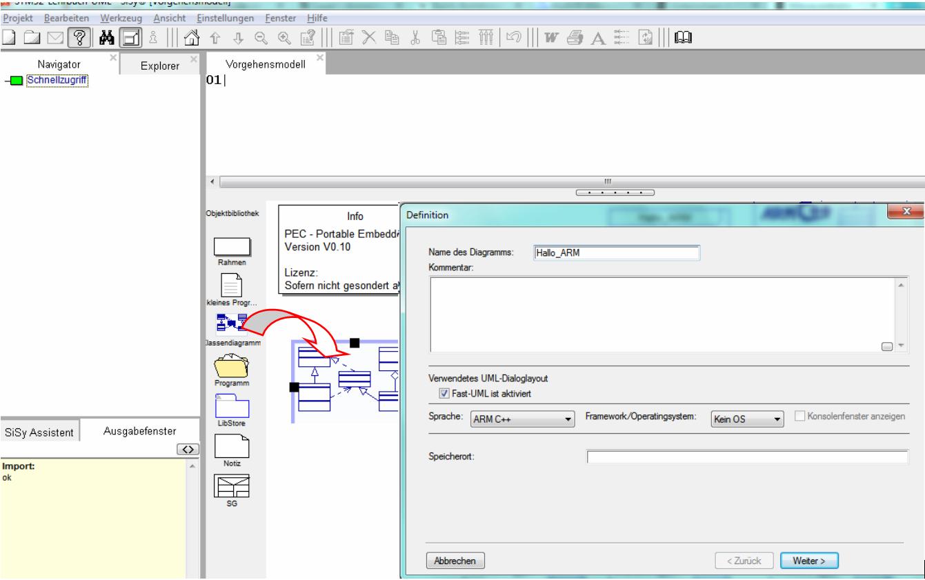
- create a new class diagram
- Target language ARM C ++
- Target platform STM32F042 mySTM32 Board light HAL
- Load diagram template application framework for PEC applications (XMC, STM32, AVR)
- Assign driver package for STM32F0
- optionally assign template stm32F042_48Mhz


Solution idea
The task is to gently fade an LED up and down for the human eye. A corresponding PWM signal should be generated for this purpose. PWM is not an analog but a digital signal in the form of a rapid sequence of pulses with different widths. Each pulse always corresponds to the full available voltage, in our case 3.3V, the pauses between the pulses are 0V accordingly. The ratio between high and low results in the desired effective voltage.

There is the possibility of using TIMER 3 Channel 3 for pin B0. The PecPwmChannel library element is available to us in the PEC Framework. This component has all the necessary features to dim our LED.

This results in the following rough draft.


The concrete hardware connection Timer3, Channel3, PinB0 must take place in the implementation.

REMEMBER: PWM = Timer + Channel + Pin
Realization
The implementation should contain the elements described in the above draft. In addition, the specific hardware connection for Timer3, Channel3 and PinB0 must be made. To do this, we look for the corresponding elements in the Explorer, drag and drop them into the diagram and connect them to the Led class Pwm . For the slow fade in and out we need a variable as a counter. We create this as an attribute with the name duty of the class controller . Since the library block controls the PWM signal from 0 to 1000, we need at least a 16 bit value. Use the following illustration as a guide when realizing your design:

In this example, the timer must be initialized and started with the desired PWM frequency. The PWM frequency should not be below 60 Hz for the eye, but not below 200 Hz for the ear (hum of power amplifiers in real applications) should not be too fast either. Frequencies that are too high can lead to undesired effects, depending on the length of the cable and the device being controlled. So we should avoid going too far into the kilohertz range. Add the following code to the onStart () operation of the Controller class.

Controller::onStart():void// boot sequence after start SysTick // Initialisierung PWM Channel // startet Timer mit gewünschter PWM Frequenz pwm.configHz(1000);
First we develop a simple solution to let the PWM signal increase relatively slowly. For this we use the counter variable duty . The setDuty (duty) operation of the PecPwmChannel library element expects values from 0 = LED off to 1000 LED maximum brightness. This means that the counter can run from 0 to 1000 accordingly. With a little pause, we ensure that the process of slowly fading in is really slow enough for the eye. Record the following code in the onWork () operation of the Controller class.

Controller::onWork():voidduty++; if (duty>=1000) { duty=0; } pwm.setDuty(duty); waitMs(1);
Test
Compile the program. Correct typographical errors if necessary. Transfer the executable program to the program memory of the controller.
- Connect the red LED to pin B0
- Build application (compile and link)
- Upload the application
- Test the application


Solution variants
The first simple solution produced the following waveform:

With this signal you can see that the LED is fading in quite well, but it's not really nice. The next solution should also implement the slow dimming of the LED. To do this, we need to generate the following waveform:

The counter must therefore be applied in such a way that the rising signal is also followed by the falling signal.
Change the code of the onWork () operation of the Controller class as follows:

Controller::onWork():voidduty++; if (duty<1000) { pwm.setDuty(duty); } else if (duty<2000) { pwm.setDuty(2000-duty); } else { duty=0; } waitMs(1);
Build, upload and test this application variant.
You can now clearly see the fading in and out of the LED.
But even this signal course does not yet appear really pleasant to our eyes. This is because we do not perceive brightness in a linear manner. The eye perceives small changes in brightness in the lower area quite well. From 50% at the latest, we can barely see the change in brightness. One solution is to make the signal course not linear but exponential. For example, it could look like this:

The formula POWER (X, Y) can be used to experimentally determine the desired signal curve in 1000 steps in Excel. The result is roughly POWER (1.00693; Step) . The corresponding C / C ++ function is pow (x, y) and can be found in # include “math.h” . To do this, a corresponding entry must be made in the Controller class. Select the class Controller and choose the menu item Define … in the context menu (right mouse button). In the Declarations / Implementation dialog, please add the following line:

Controller::onWork():void//--------------------------------------------------------------------- // breathing LED with exponential function pwm 0-1000 #include "math.h" duty++; if (duty<1000) pwm.setDuty( pow(1.00693,duty) ); else if (duty<2000) pwm.setDuty( pow(1.00693,2000-duty) ); else duty=0; waitMs(1);
Build, upload and test this application variant.
You can now clearly see the gentle fading in and out of the LED. The LED seems to literally breathe.
Video summary
Learned and established work steps:
- Create and open class diagram
- Select and load diagram template for PEC application and insert driver package for STM32F0
- Search for the desired blocks in the Explorer / Navigator and drag them into the diagram
- Aggregate classes
- Create attributes and operations of a class
- Assemble classes and templates into components
- create the necessary source code in the operations
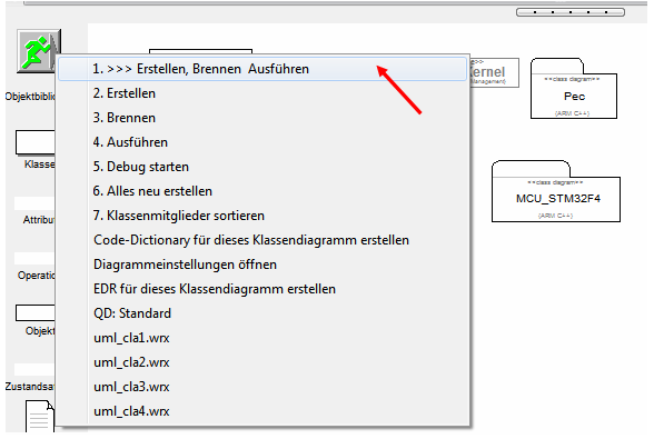
- Creating and burning an ARM application in the class diagram
- configure and use the SiSy-ControlCenter
And here this section again as a screencast.
Exercise 7
To practice, expand the application by a UART connection with 19200 BAUD to the SiSy-ControlCenter. Send the PWM values for controlling the LED as 8 bit numbers to the SiSy ControlCenter. Follow the signal curve in the ControlCenter's Osci view.
