ESE Block 8 ADC
The acquisition and processing of analog data is often essential for embedded systems. The PEC framework provides classes and templates with which a large number of tasks relating to the analog-digital converter can be carried out in a few simple steps. Many problems in which an analog value is recorded, processed and then something, whatever, is to be done can be adequately solved with a resolution of 8 bits. In this example, we therefore only want to collect an 8-bit value cyclically and send it to the control center via UART. The charm here is that 8-bit values can be transmitted very smoothly via UART, as this “randomly” transmits data words of 8 bits each.
In an extension of the exercise, we will not send the value directly as 8-bit raw data (binary raw data), but convert the values into readable characters (ASCII) and send them as a character string to the PC. The previous UART exercise can serve as a template here.
The task
 A microcontroller application is to be developed in which the analog values are digitized by a potentiometer and sent to the PC.
Requirements for the solution:
- UART on A9 / A10
- Data transfer rate 19200 BAUD
- Accuracy of ADC conversion 8 bit
- Potentiometer or brightness sensor on pin A7
Preparation
Perform the following preparatory work:
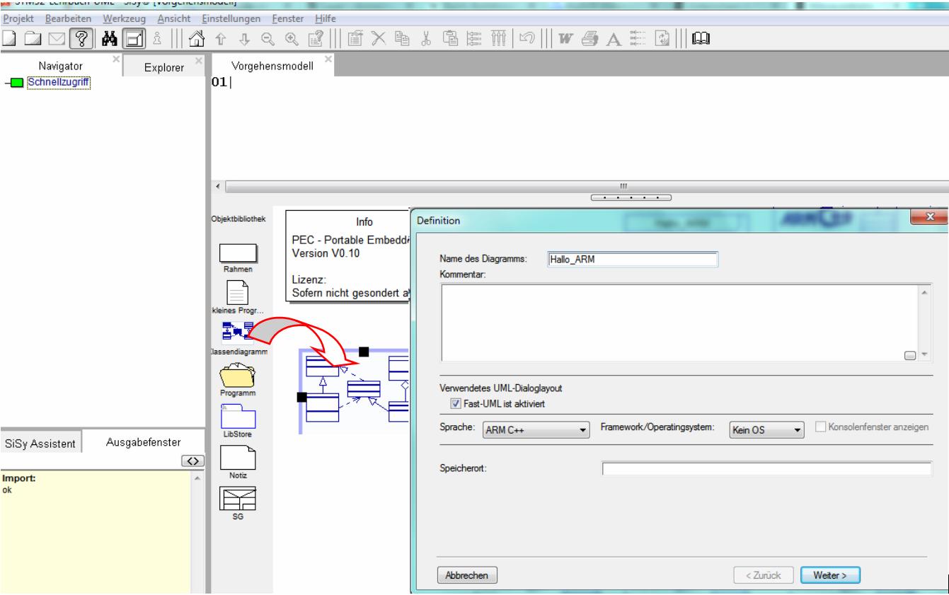
- create a new class diagram
- Target language ARM C ++
- Target platform STM32F042 mySTM32 Board light HAL
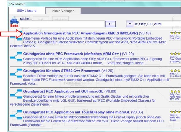
- Load diagram template application framework for PEC applications (XMC, STM32, AVR)
- Assign driver package for STM32F0
- optionally assign template stm32F042_48Mhz

Solution idea
 If we visualize the task, it then consists of recording measurement data from an analogue sensor (potentiometer / brightness sensor) with our microcontroller and displaying them in a terminal program on the PC. The following system modules for the class model of our solution result from this task.


The STM32F042 has an analog-digital converter ADC with up to 12 bit accuracy, up to 10 different channels and a recording time of 1 microsecond to acquire analog data. The voltage range of the recorded analog values is between 0V (GND) of the supply voltage or the reference voltage of the ADC 3.3V (AVCC).
The PEC framework offers us the already known element PecUart for the solution of the set tasks and the modules PecAdcSingle and PecAdcChannel for the use of the ADC.

The small module PecAdcSingle would be absolutely sufficient for the requirements. Since we don't have to be “economical” for this exercise, we use the somewhat more complex PecAdcChannel library block. This means that we can conveniently record several analog channels later. If we take over the worked out system and library modules, a possible rough draft of our solution looks like this:

REMEMBER: Signals (voltages) on the controller = maximum up to the supply voltage !!!
Realization
The implementation should contain the elements described in the above draft. In addition, we still have to assign the specifically used resources to our controller. For the UART we use the familiar configuration from the previous exercise uart1portA9_stm32f0 . We should connect the ADC to PinA7. We could use other pins, but pin A7 is simply the closest to the analog input devices on our board. We consult our reference card again.

As a result, pin A7 is also the ADC channel 7. Now we have all the information we need to complete our draft solution. Here's a quick summary:
- Basic framework with system module Controller
- Create system modules Sensor and Terminal
- connect new system modules with controller (aggregation)
- Assign library blocks PecUart and PecAdcChannel (implementation)
- Configure module Terminal correctly with baudrate19200 and uart1portA9_stm32f0
- Configure module sensor correctly with adcResolution8bit and adc1ch07_stm32

Complete your class model so that it corresponds to the following illustration. Arrange the elements clearly.

For the sake of simplicity, we take care of the cyclical acquisition of the analog value and send it to the PC in the onWork operation. So that we can follow the changes in the values in peace, we ensure that the data are not sent too quickly one after the other with a short waiting time.

Controller::onWork():void// continuous event from the Mainloop uint8_t value; value=sensor.getValue(); terminal.writeByte(value); waitMs(10);
Test
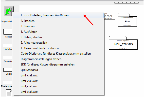
Compile the program. Correct typographical errors if necessary. Transfer the executable program to the program memory of the controller.
- Build (compile and link)
- upload
- connect the photo sensor or the potentiometer to pin A7


Start the ControlCenter and note the correct settings for the COM port. After you have opened the connection with, switch the view to “Osci”. You can use the options for the Oscilloscope view to select different display variants. Now you can follow every change on the potentiometer on the screen.


Extension
For more precise measurements it is necessary to increase the resolution of the ADC. The STM32F042 can digitize analog values with a resolution of up to 12 bits. Unfortunately, the 12 bits can no longer be sent to the ControlCenter so easily to visualize them. The UART is byte-oriented (8 bits). If data is to be composed of several bytes, the receiving program must know exactly how the information is to be composed. Simple terminal programs cannot do that. A relatively comfortable way of transferring our 12-bit data is to convert it into text. Then the values can be easily followed in the text view. Please add the attribute buffer of type String in the controller class.

Change the code of the operation onWork as follows:
Controller::onWork:
uint16_t value;
value=sensor.getValue();
buffer.format("Adc=%d\n",value);
terminal.writeString(buffer);
waitMs(1000);

Compile the program. Correct any spelling mistakes. Transfer the executable program to the program memory of the controller. Start the ControlCenter, note the correct settings for the COM port. After you have activated Connect , set the view to Text . Test the extended application and vary the settings of the potentiometer.

Video summary
Learned and established work steps:
- Create and open class diagram
- Select diagram template for PEC application, load and insert driver package for STM32F4
- Search for the desired blocks in the Explorer / Navigator and drag them into the diagram
- Aggregate classes
- Create operations of a class
- Create attributes of a class
- Assemble classes and templates into components
- create the necessary source code in the operations
- Create and burn an ARM application in the class diagram
- use the PecAdcChannel library block
- use the SiSy ControlCenter
Here is our usual video summary.
Exercise
To practice, add an ErrorLED to the application. The ErrorLED should light up for sensor values below 100.