ESE Block 7 UART
This section is about communication with the PC. For a large number of embedded systems it is necessary to communicate with other systems. There are many different variants for this. One of the most important communication options is the good old serial interface. The older ones among us still know them. We used to connect the mouse there. There are different names for this communication interface. Depending on the environment you are in, the serial interface comes across as COM, TTY, RS232, RS485, UART, USART, USIC or SERCOM. In our microcontroller this is called UART (Universal Asynchronous Receiver Transmitter) or USART (Universal Synchronous Asynchronous Receiver Transmitter). In the PC, although we are using a USB connection, this appears as a COM port. You can see this in the device manager under Connections (COM & LPT). This is ensured by a small controller called a USB-UART bridge. The COM port in the device manager is only simulated by the corresponding device driver. One also speaks of a virtual COM port (VCP). We will use this COM port for this task.
The Task
 The task should be to send data to the PC via UART. There the received data is displayed in a terminal program. Generate changing data by incrementing a counter by 1 and sending this value.
Requirements for the solution:
- Data transfer speed 19200 baud
- USB-UART-Bridge at pin A9 / A10 (already firmly connected)
- Use 8 bit counter
- Send a maximum of 100 values per second
Preparation
Perform the following preparatory work:
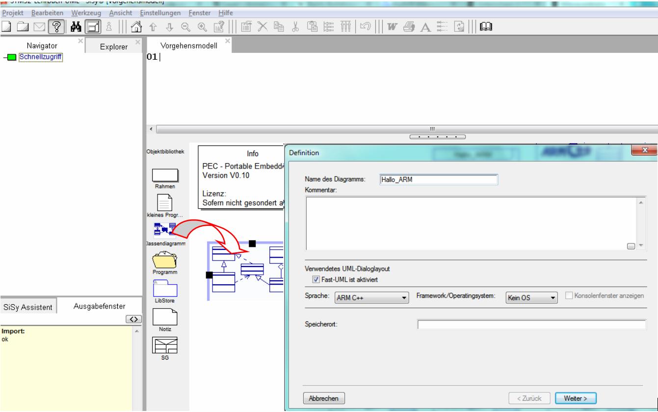
- create a new class diagram
- Target language ARM C ++
- Target platform STM32F042 mySTM32 Board light HAL
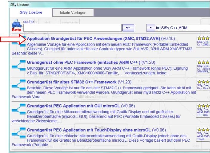
- Load diagram template application framework for PEC applications (XMC, STM32, AVR)
- Assign driver package for STM32F0
- optionally assign template stm32F042_48Mhz

Solution idea
The task is to configure the UART at pins A9 / A10 with 19200 baud and to send data to the PC via this interface. The connection of the USB-UART bridge to pins A9 and A10 of the controller is already built into the board. You are already using this the whole time when programming via the bootloader.
So-called terminals are used to receive serial data. In older versions of the Windows operating system, such a terminal program could still be found under the Accessories section. It was called HyperTerminal . This program comes from a time when so-called modems were still used to establish communication links between computers over the normal analog telephone network. Well then the internet came and that was it for the HyperTerminal as an operating system component.
Such a program is still important for embedded developers to communicate with their microcontroller. That is why SiSy has a special terminal program called the ControlCenter . We abstract the UART connection to our terminal as a new system module as follows:


The PEC framework offers the PecUart template and configurations for various transmission speeds as a library module for sending and receiving data via the serial interface.

 We need the PecUart and baudrate19200 from the UART package as library elements for configuration. The configuration of the data transmission must match exactly on both the PC terminal and the microcontroller. If the settings are not identical, the data transfer will be faulty.
We use the following configuration for data transfer:
- 19200 baud
- 8 data bits (default)
- no parity check (default)
- 1 stop bit (default)
The rough draft for this solution looks like this:

REMEMBER: UART = always configure the data transmission speed in BAUD
Realization
The implementation should contain the elements described in the above draft. In addition, the correct UART configuration must be added. ARM controllers have a bus matrix. This means that internal components such as a UART are not permanently connected to the corresponding pins, but the hardware / software developer can choose from several possible pin configurations. The relevant information can be found in the documentation for the controller (data sheet, reference manual, …). At the beginning of the tutorial we recommended you to print this Referencesheet and place it next to the keyboard. Now is a good time to look at the reference card. Here you will find the relevant information to determine the correct UART configuration.


You can find the library element uart1portA9_stm32f0 via the Explorer. You can also use the little question mark button on PecUart [?].

We generate the data that we want to send to the PC with a simple counter. We create the variable for this counter as a attribute of the controller class.

Your class model should correspond to the following illustration after the corresponding work steps.

Now all that's left to do is code the required behavior. The simplest solution is:

Controller::onWork():void// continous event from the Mainloop counter++; terminal.writeByte(counter); waitMs(10);
Compare this solution with the following alternative approach.

Controller::onWork():void// continous event from the Mainloop counter++; String txt; txt.format("\n Hallo mySTM32, counter= %d",counter); terminal.writeString(txt); waitMs(10);
Test
Compile the program. Correct any spelling mistakes. Transfer the executable program to the program memory of the controller.
- Build (compile and link)
- upload
- connect …


Compile the program. Correct any spelling mistakes. Transfer the executable program to the program memory of the controller and start the ControlCenter tool.
- Build (compile and link)
- upload
- Tools menu, ControlCenter
Set the parameters for the connection to the board in the ControlCenter. Pay attention to the correct COM port and the correct baud rate. The COM port can be found in the device manager if necessary.

Now you can receive the desired data from the controller.

Video summary
Learned and established work steps:
- Create and open class diagram
- Select the diagram template for the PEC application, load it and insert the driver package for the STM32F4
- Search for the required modules in the Explorer / Navigator and drag them into the diagram
- Assemble classes and templates into components
- create the necessary source code in the operations
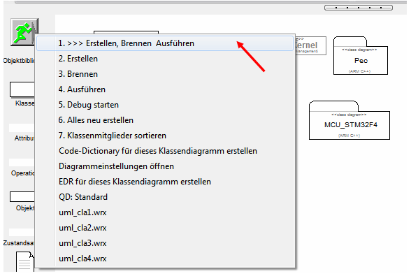
- Creating and burning an ARM application in the class diagram
- Use the PecUart library block
- configure and use the SiSy control center
And here this section again as a video summary.
Exercise
Add a button as a Send button to the system solution. Change the solution so that the data transfer takes place in the 100 millisecond system event onEvent100ms () when the Send button is pressed.