ESE Block 6 SysTick
With their performance, ARM controllers are predestined for the use of corresponding runtime environments or suitable real-time operating systems. These are mostly based on a timer-triggered distribution of resources, especially the resource computing time. The ARM has a special timer for this, which has the sole task of generating a system trigger event.
Even without a real-time operating system, this SystemTick is very interesting for the application developer. The program templates used here in the tutorial are already prepared for the use of the SysTick or are based on it. In the PEC framework, the library we are using here, a 10 millisecond event is generated by default from the SysTick for the PecAppKernel . The PecAppKernel distributes the following events to all AppModules:
- 10 millisecond event onTimer10ms() directly from the Interuppt treatment
- 100 millisecond event onEvent100ms() via an event queue
- 1 second event onEvent1s() via an event queue
We will use these events for this exercise. At the same time, you should gain a certain understanding of how to use PecFramwork timing.
The task
 A microcontroller application has to be developed in which the user sees how the SysTick of the microcontroller works.
The task is: Develop a solution for this in which the various SysTick events (10 ms, 100 ms, 1 s) of the microcontroller are made clear by different flashing LEDs and a beep from the speaker. The LEDs should be connected to pins B0, B1, B3 and the speaker to pin B4.
Preparation
Perform the following preparatory work:
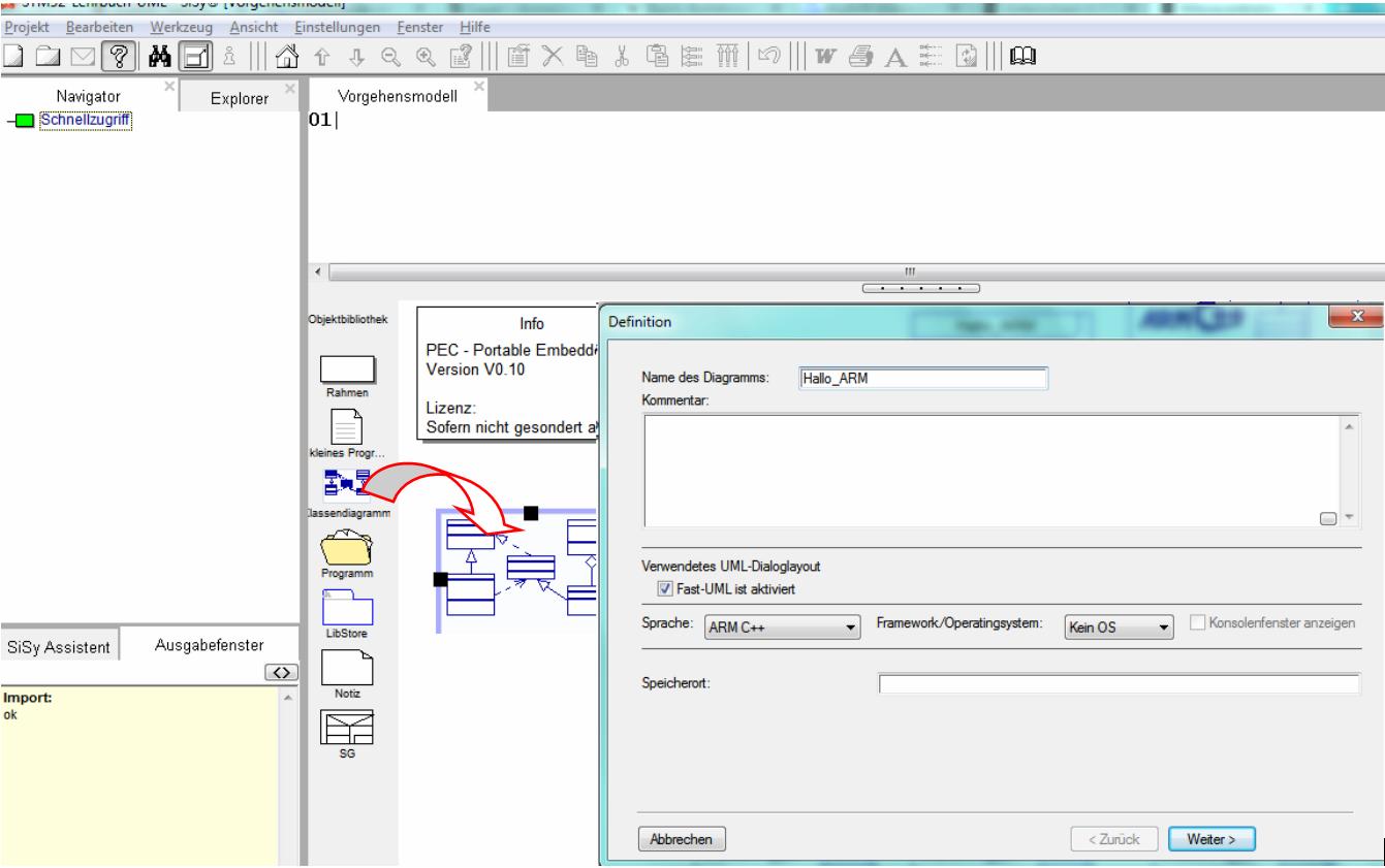
- create a new class diagram
- Target language ARM C ++
- Target platform STM32F042 mySTM32 Board light HAL
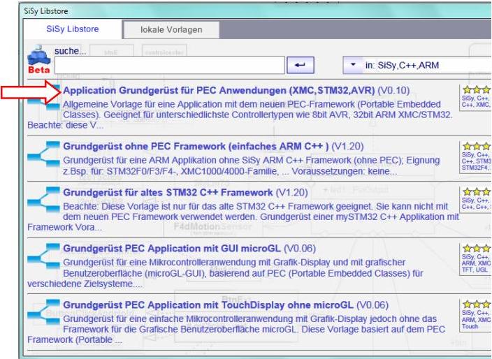
- Load diagram template application framework for PEC applications (XMC, STM32, AVR)
- Assign driver package for STM32F0
- optionally assign template stm32F042_48Mhz

Solution idea
The task is to demonstrate the concept of the system timer with the resulting system events in a suitable form. As feedback for the user, we use optical signals, these are flashing LEDs and an acoustic signal, this is the speaker.
First to the 10 milliseconds event. This event is called directly from the interrupt function (interrupt service routine or interrupt handler). For the application developer, this means that this function must only be used in exceptional cases and if so, only with very little, i.e. fast, code, as otherwise we slow down the system. We recognize that this is an event by the prefix on in the operation onTimer10ms () . The 10 milliseconds are far too fast to be perceived as a flashing LED. That's why we put the signal on the speaker because we can hear frequencies well into the kilohertz range.


The event for the 100 milliseconds is not called directly from the interrupt function but goes via an event queue. This means that events are placed in the queue according to their sequence and, if the system has enough time, they are processed. Although this leads to a delay of a few microseconds (latency) between the occurrence of the event and the processing of the event reaction, the system can manage the processor time used much better and the system still runs smoothly. We recognize this by the identifier Event in the event name onEvent100ms () . Here we can easily connect an LED. The 100 milliseconds between each switchover results in 5 Hertz, which we easily perceive as blinking.


The 1 second event is nice and slow. So here too we use an LED for visualization.


To compare and to clarify the parallelism of this event-oriented programming concept, we add a flashing LED with a software PWM (dimming) based on the wait function waitUs in the onWork event. This is a good opportunity to talk about the characteristics of the onWork () event. This event is called from the so-called Mainloop . This means onWork is always called when no other events are being processed. This is often 90 or 99% of the available processor time. It follows that in onWork we accommodate everything that does not depend directly and promptly on a hardware interrupt, the processing of which therefore usually does not map any time-critical tasks. For the visualization of the running of onWork we also use an LED again. We have enough computing time in onWork for a simple algorithm for dimming the LED.


In summary, we therefore need the following system components:


These need to be related again. The PecPinOutput library is completely sufficient for the requirements (toggle). The rough draft looks like this:

REMEMBER: Prefix ON = one event
Realization
The implementation should include the elements described in the rough draft above. In addition, the specific output pins must be assigned to the system components again.

Complete your class diagram as follows:
- Create classes RedLED, YellowLED, GreenLED and connect to the controller (aggregation)
- Create class Speaker and connect to the controller (aggregation)
- Use PecPinOutput as library block for the created classes
- Assign pins B0, B1, B3 and B4 to the system components (B2 is not available in the given housing shape)
Your class model should now look like the following picture. Verify your model and arrange the elements clearly.

In the next step we attach ourselves to the system events for 10, 100 and 1000 milliseconds by dragging operations to the class controller and inserting the following functions for event handling step by step:
- onTimer10ms ()
- onEvent100ms ()
- onEvent1s ()

Nach diesen Arbeitsschritten sollte ihr Klassenmodell dem folgenden Bild entsprechen. Verifizieren Sie ihr Modell und ordnen Sie die Elemente übersichtlich an.

To implement the required functionality, we add the following codes to the respective event functions. First we let the red LED blink. To do this, we control the red LED in the 100 millisecond event as follows.

Controller::onEvent100ms():voidredLED.toggle();
The green LED should flash the slowest. We use this for the 1 second event.

Controller::onEvent1s():voidgreenLED.toggle();
In contrast, the fast 10 millisecond event. Here we toggle the speaker.

Controller::onTimer10ms():voidspeaker.toggle();
Here, too, the actual effort that we have to put into writing lines of C ++ code is comparatively low. The main part of our work lay in the construction of a suitable class structure and in the use of the prepared timing in the PEC framework. Now we can test the application.
Test
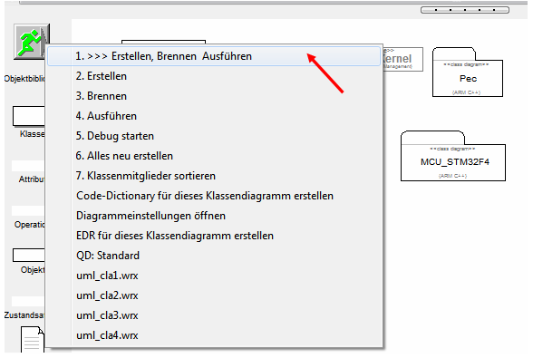
Compile the program. Correct any spelling mistakes. Transfer the executable program to the program memory of the controller.
- Build (compile and link)
- burning
- connect …


Extension
Next we expand the application so that we use the onWork() event, which is continuously triggered from the mainloop of the runtime environment of the framework, to let the yellow LED glow very weakly (dim). The visible and audible runtime behavior of the other output devices should not be influenced. Therefore we do not use long wait functions like waitMs () .

Controller::onWork():void// continuous event from the Mainloop uint8_t brightness=1; // use here 1 to 255 for fix brightness of the yellow LED yellowLED.on(); for (int i=brightness; i>0; i--); yellowLED.off(); for (int i=255-brightness; i>0; i--);
Build, upload and test this extension. Experiment with different values of the variable brightness (1-255);
Variant
We can extend the dimming of the yellow LED by fading the LED up and down independently. Try the following variant. You will find that this rather complex solution does not noticeably affect the runtime behavior of the other LEDs and the speaker.

Controller::onWork():voidstatic uint16_t dim=0; if (dim < 1000) { yellowLED.on(); waitUs(dim); yellowLED.off(); waitUs(1000-dim); dim++; } else if (dim <2000) { yellowLED.on(); waitUs(2000-dim); yellowLED.off(); waitUs(dim-1000); dim++; } else { dim=0; }
Go deeper into the meaning of the static keyword in C / C ++ and why this keyword was used in the above solution.
Video summary
Learned and established work steps:
- Create and open class diagram
- Select diagram template for PEC application, load and insert driver package for STM32F4
- Switch navigator to UML packages
- Find the desired LED class in the Navigator / Explorer and drag it into the diagram
- aggregate class
- Create operations and insert them into a class
- Overwrite operations of a base class
- create the necessary source code in the operations
- Create and burn an ARM application in the class diagram
And here this lession again as a video summary.
Exercise
To practice, change the application as follows:
- Change: Comment out the code in onTimer10ms and let the speaker toggle in onWork .
Create and test this changed application.
Compare and evaluate the acoustic result.- The tone is much higher. What does that mean?
- The sound is not continuous but has interference. Why?
- Change: Add a waiting time of 500 ms to onWork with waitMs .
Create and test this modified application.
Compare and evaluate the optical and acoustic result.- The sound is just a crack.
- The timing of the flashing LEDs has changed.
From the result of these changes, draw conclusions for the application of wait functions.