The first blinky
Well begun is half done. The first exercise with the probably unfamiliar environment should be to simply switch on an LED.
The sense and purpose of class libraries is, of course, above all to ensure that things that are used frequently or typical problems that have simply been solved before, are convenient for the user Reuse available. We will use that.
The task
 The object orientation is characterized by increasing abstraction from the actual internal structure and the internal behavior of the machine towards a user-related perspective.
The task is:
The user should see that the microcontroller is working. Develop a solution for this that shows the state of the microcontroller by flashing an LED. This indicator LED should be connected to port B0.
Preparation
If you have now opened the previous class diagram, select the menu item up in the context menu (right mouse button) of the diagram. If the project is no longer open, open the SiSy UML project again.
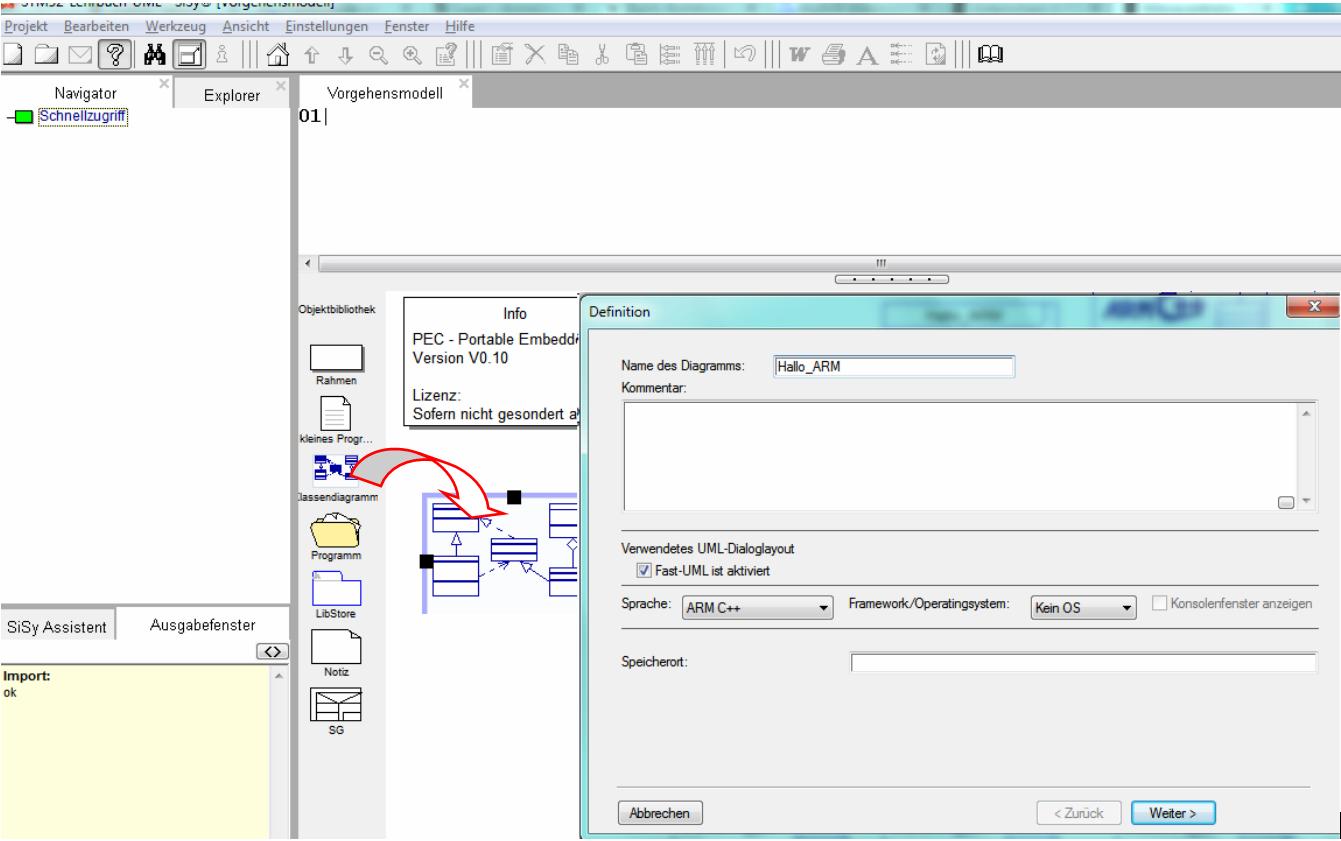
- Create a new class diagram and
- choose the language ARM C ++ .
- Note the settings for the target platform STM32F042 mySTM32 Board light HAL .
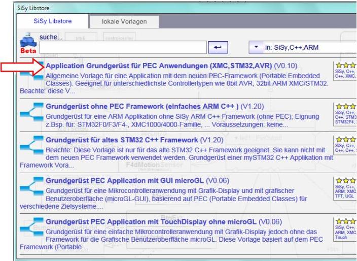
- When opening the diagram (right mouse button, downwards) you load the diagram template Application basic structure for PEC applications (XMC, STM32, AVR) from the SiSy LibStore.
- Assign the driver package for STM32F0 .
- You can also use the library block stm32F042_48Mhz from the Explorer to operate the controller with full 48MHz performance.

Solution concept
The task is to control an LED to display the status of the controller. If we follow the so-called object-oriented concept, this StatusLED is a component of our system. We map system modules as classes in the UML. We can already see such a system building block in our class diagram. The controller.


Now we need a class for the traffic LED.


These two building blocks are related to each other. As a beginner, please only use two types of relationship between building blocks. That's the “is a” relationship and the “has” relationship. The “is a” relationship between the controller and the LED makes little sense because the “has” relationship fits better. We can map a “has” relationship with the “aggregation” in the UML. The aggregation is shown in the UML as an arrow with a diamond shape at the beginning. The code generator turns it into a class attribute. The name and visibility of the attribute can be seen on the arrow. The class name should always start with a capital letter. We always write attributes and operations in lower case at the beginning.


Furthermore, we don't want to program so much ourselves, but rather use the convenience of the available PEC library. A PEC block suitable for this task is PecPinOutput . If we look at the PecPinOutput library block, we will see that it does exactly what we need to switch an LED on or off.

 The relationship between StatusLED and PecPinOutput can be mapped as “is a” relationship.
In this case we use the UML implementation .

This illustration can be read very nicely for verification as follows:
The controller has a status LED. The StatusLED is a PecPinOutput.
That is a very useful rough draft. The assignment to the specific pin on the controller and the actual logic for switching on the status LED are still missing. We leave that to the realization. The rough draft of the required functionality can be seen on the right as an activity diagram.
REMEMBER: System element = class
REMEMBER: “has” relationship = aggregation or composition
REMEMBER: “is a” relationship = realization or inheritance
REMEMBER: Class names = always a capital letter at the beginning
REMEMBER: Attributes and operations = always start with a small letter
Realization
The implementation should contain the elements described in the above draft. In addition, the Pin B0 must be linked to the implementation of the StatusLED . You can find the corresponding PEC block via the Explorer. You can also use the small question mark at PecPinOutput . Use the following illustration as a guide when realizing your design:

The first time we go through this step by step.
First drag a class from the object library into the diagram and give it the name StatusLED .

Then connect the Controller class with the StatusLED class and select Aggregation as the connection type.

Search for the PEC library block PecPinOutput in the Explorer. Drag this element onto the diagram.

Connect the PecPinOutput library block with the StatusLED class. Select Realization as the connection type.

Search for the pinB0 library block using the Explorer. Drag this block into the diagram. You can also use the small question mark button to get a list of the possible building blocks.

Connect the module pinB0 with the class StatusLED . Select Realization as the connection type.

Following these steps should give you a design similar to the following illustration. Arrange the elements clearly. Class diagrams are very useful means of documentation. Compare your design with the illustration below.
This software construction drawing can be “read” as follows:
- the central component is the controller (application class)
- this has the behavior features (operations) onStart and onWork
- The controller is a PecAppKernel
- The global object app is the instance of the application class controller
- The controller has a StatusLED with the attribute name statusLED
- The statusLED attribute of the Controller class is public
We note the actual behavior logic for the blinking of the LED as C ++ code in the onWork () operation of the Controller class. To make the LED flash, we switch the LED cyclically (toggle). So that the eye can perceive this toggling, we include a short break. The options offered by the PecPinOutput library block are shown on the right. Record the following code in the onWork operation:


Controller :: onWork (): void// continuous event from the main loop statusLED.toggle (); waitMs (200);
Compare this code with the following alternative solution:

Controller :: onWork (): void// continuous event from the main loop statusLED.on (); waitMs (50); statusLED.off (); waitMs (200);
Test
Compile the program. Correct any spelling mistakes. Transfer the executable program to the program memory of the controller.
- Build (compile and link)
- upload
- connect pin B0 to the red LED


Video summary
Learned and established work steps:
- Create and open class diagram
- Select and load diagram template for PEC application and insert driver package for STM32F0
- Find PEC blocks in the Navigator / Explorer
- Drag the desired library elements into the diagram
- Connect classes with each other ( aggregation , realization )
- create the necessary source code in the correct operations
- Create and burn an STM32 application in the class diagram
And because it was so beautiful, here the whole thing again as a video.
Exercise
For exercise, add another ErrorLED to pin B1. Orientate yourself to the above work steps. Let the ErrorLED blinking in the opposite order to the StatusLED.