ESE Block 14 CAN
Use the CAN bus with the mySTM32 light. This exercise should be carried out in pairs or two mySTM32 light boards are required for this exercise.
In the previous tutorial you got to know the I²C bus. This bus is used to connect different controllers, for example on a printed circuit board. If the controllers to be networked are further apart, for example, a few meters of cable length can quickly come together for the sensors and actuators on a construction machine, other fieldbus systems are used. The CAN-Bus is a frequently used bus system, especially in the vehicle sector. CAN stands for Controller Area Network. The name suggests that this is a network protocol for microcontrollers. In contrast to the I²C protocol, so-called Frames are sent with the CAN. These consist of control information such as the message ID and the user data to be transmitted. In the standard mode, the frame offers 8 bytes or 8×8 = 64 bit user data. In the CAN, the information is usually not sent once in an event-oriented manner, but cyclically with a certain update rate, for example every 20 or 100 milliseconds. The update rate correlates with the importance of the message. The absence of a message implies the failure of the corresponding node.
The task
 Two controller boards are to be networked via the CAN bus. Each board should have a button and an LED. When you press the button, the LED on the other board should light up.
Requirements for the solution:
- Send button on pin A0
- Receive LED on pin B0
- CAN update rate 100 milliseconds
- Message IDs Board 1 = 1, Board 2 = 2
Preparation
If you have still opened a class diagram, select the menu item “up” in the context menu (right mouse button) of the diagram. If the project is no longer open, open the SiSy UML project again. Perform the following preparatory work:
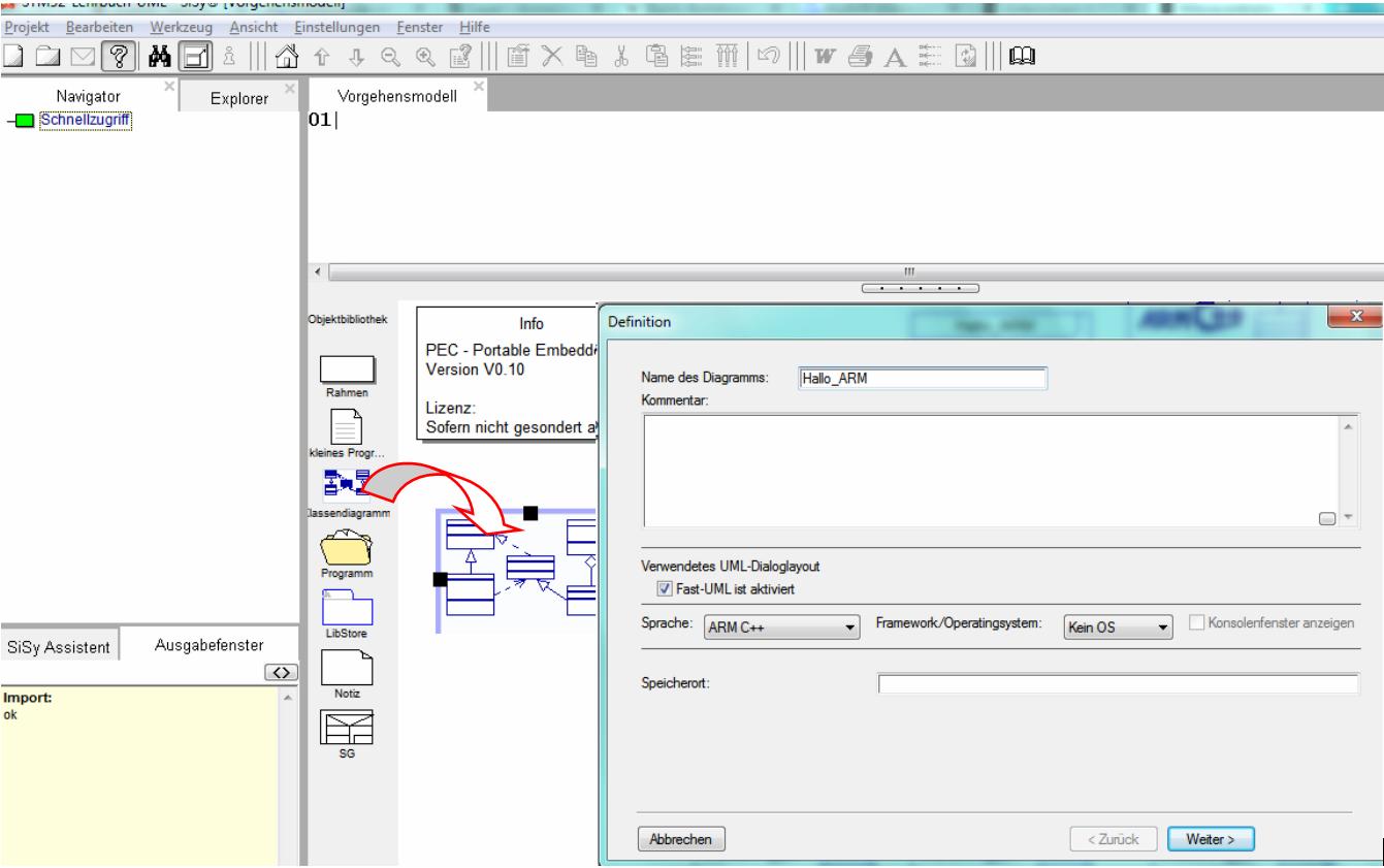
- create a new class diagram
- Target language ARM C ++
- Target platform STM32F042 mySTM32 Board light HAL
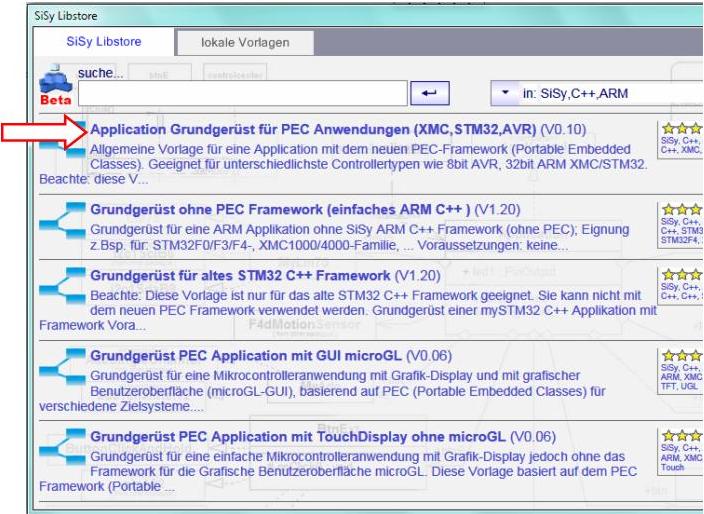
- Load diagram template application framework for PEC applications (XMC, STM32, AVR)
- Assign driver package for STM32F0
- optionally assign template stm32F042_48Mhz

Solution idea
Implementing a CAN bus solution is a bit more complex. It is necessary to study the CAN bus in more detail . Before we start, we should be clear about the following aspects:
- System states are cyclically placed (sent) on the bus as messages
- Messages do not have recipient addresses but an ID of the system status shown
- Each controller can receive the system states that are important to it and react to them
- Controllers can / must filter out the desired messages (IDs)
- the system status (s) are encoded in 64-bit user data (8 bytes)
Let's try to find out the important building blocks for the system design. The system status to be sent is a button. Incidentally, only 1 bit is required in the message to be sent for coding the button status. The controller evaluates the button cyclically, for example every 100 milliseconds, encodes the status (0/1) in a CAN message and sends this on the CAN bus. The receiving controller filters and decodes the received message from the CAN bus and switches the LED accordingly.


The package “Middleware / CanSupport / pec_Can” contains suitable library modules for the task at hand. There are modules for the CAN bus and the send and receive messages. The elements that are important for the solution are marked in the following illustration.

The following rough drafts of the CAN solution can be derived from the worked out system modules.
First the rough draft for the transmitter solution.


In addition, the corresponding draft of the recipient solution.

The CAN protocol is not part of the PEC basic packages but rather is contained in the middleware package. To use the CAN library blocks, it is necessary to include the corresponding driver package “pec_can” from the “Middleware / CanSupport” folder in the class diagram.
REMEMBER: use middleware = assign appropriate package
Realization
First of all, the transmitter solution has to be implemented. Make sure to include the package pec_can in the class diagram.
A brief summary of the necessary actions:
- prepare new class diagram
- Include package pec_Can
- Create and connect classes SendButton , CanBus and SendMessage
- Link library modules PecButtonClickAndHold , PecCanBus , PecCanMsgSend
- Connect specific controller resources pinA0 and canPortA11A12_stm32f0
- Overwrite * Operation onEvent100ms of the Controller class
- Overwrite the * Operation onConfig of the SendMessage class

In the onConfig() operation of the MessageRecive class, we assign ID 1 to the message object.

SendMessage::onConfig():voidmsgId=0x01;
We use the 100 millisecond event of the Controller class for the cyclical sending of the status of the button. We code the button status in the first data byte of the message with 0 for not activated and with 1 for button activated.
Controller::onEvent100ms():voidif (sendButton.isPressed()) { canBus.sendMessage.msgData.data8[0] = 1; } else { canBus.sendMessage.msgData.data8[0] = 0; } canBus.sendMessage.send();

Then the receiver solution can be implemented. Make sure to include the package pec_can in the class diagram.
A brief summary of the necessary actions:
- prepare new class diagram
- Include package pec_Can
- Create and connect classes ReciveLED , CanBus and ReciveMessage
- Link library modules PecLed , PecCanBus , PecCanMsgRecv
- Connect specific controller resources pinB0 and canPortA11A12_stm32f0
- Overwrite * Operation onRecive of the ReciveMessage class
- Overwrite * Operation onConfig of the ReciveMessage class

So that the correct message is received, we assign ID 1 to the expected received message.

ReciveMessage::onConfig():voidmsgId=0x01;
We simply implement the decoding of the message in the reception event of the message object.
ReciveMessage::onRecive():voidif (msgData.data8[0] == 1) { app.reciveLED.on(); } else { app.reciveLED.off(); }

Test
Translate the solutions. Correct typographical errors if necessary. Transfer the executable programs to the controller's program memory.
- Build (compile and link)
- burning
- Connect button 1 with A0 and the red LED with B0 on the boards accordingly
- Establish a CAN connection between the boards, note CAN Hi = Hi, GND = GND, Lo = Lo


Video summary
Learned and established work steps:
- Create and open class diagram
- Select diagram template for PEC application
- Load the correct driver package
- Include middleware packages
- Search for the desired modules in the Explorer and drag them into the diagram
- Aggregate classes, form components
- Overwrite operations
- create the necessary source code in the operations
- Create and burn an ARM application in the class diagram
And because it was so beautiful, here the whole thing again as a video.
«« ATTENTION OLD VIDEO »»
Exercise
Expand both solutions so that they each have a send button and a receive LED and board 1 sends to 2 and board 2 to a.