ESE Block 11 INT
Evaluate external interrupts. In the previous exercise we used a timer as an internal trigger. In the case of embedded systems, however, external triggers are at least as important as the use of timers. Examples can be counted endlessly, in a car we find switches as triggers for system actions on all doors, the tailgate or trunk lid, seat belts, the lighting system, window lifters, lots of switches for the driver in the cockpit area and on the steering wheel, etc. etc. All these switching elements no longer clumsily switch anything on or off. The signals from these system modules are processed by microcontrollers. This could of course be done by constantly polling the switches. With the large number of signals to be evaluated, this can consume a considerable amount of computing time which is then not available for other tasks. This means that the detection of changes (rising or falling edges) at the signal inputs and the triggering and processing of hardware events, i.e. interrupts, are of great importance, because event-oriented processing consumes significantly less computing time and can also consider signal priorities much better.
The task
 A microcontroller application is to be developed in which an external signal, a falling edge, triggers an activity on the controller. The reaction of the controller to the external event should be realized by switching an LED.
The solution should meet the following requirements:
- External signal, falling edge, via button on A0
- LED display on pin B0
- No constant polling of the button (polling)
- Handling of the event directly in the interrupt
Preparation
Perform the following preparatory work:
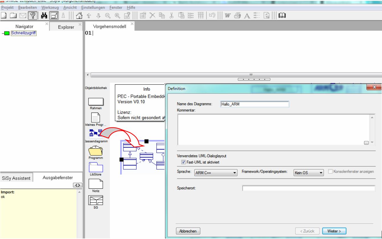
- create a new class diagram
- Target language ARM C ++
- Target platform STM32F042 mySTM32 Board light HAL
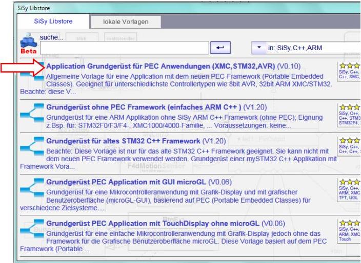
- Load diagram template application framework for PEC applications (XMC, STM32, AVR)
- Assign driver package for STM32F0
- optional template stm32F042_48Mhz assign

Solution idea
The task is to evaluate the actuation of the function key via interrupt. The display LED should switch as a reaction to the interrupt. The PEC library offers the PecPinInterrupt library block for the task of handling external interrupts.

If you take a closer look at this module, you can see that PecPinInterrupt has all the properties of PecPinInput and how it can be combined with pinPullUp and pinLowActive , for example. These options are well suited for the buttons on the mySTM32 Board light as they close to ground when pressed.


We can use PecPinOutput or PecLed for the display LED. We are now familiar with handling these modules. The following rough draft can be derived from these considerations.

This class model can be described textually as follows:
The controller has a function key. The function key is a PecPinInterrupt. The function key has an indicator LED. The IndicatorLED is a PecLed
What is new about this design is that the IndicatorLED class was not aggregated into the Controller but into the FunctionKey class. In this way a structure was built in which the FunktionKey class hides the IndicatorLED class, so to speak. Otherwise we always attached system modules to the controller. The new solution has the advantage that when the LED responds, the path via the instance of the controller does not have to be followed. Since the FunctionKey class is now the owner of the IndicatorLED , it can be used directly without any restrictions. That makes sense too. No other module in this application uses the IndicatorLED . FunctionKey and IndicatorLED now form a combined unit that is used by the controller as a single component. Compound system modules are called system components.
REMEMBER: System component = aggregation of several system modules
Realization
The implementation should contain the elements described in the above draft. In addition, the following model elements must be added.
- the specific pins A0 and B0 for the button and the LED
- pinLowActive and pinPullUp for the button
- Overwrite virtual operation onPinInterrupt () of the class FunctionKey

Orientate yourself to the above illustration when realizing the necessary work steps.

The required reaction to pressing the key (signal change: falling edge) should take place in the interrupt, i.e. in the onPinInterrupt () operation. Note the code for toggling the LED there.

FunctionKey::onPinInterrupt():voidindicatorLED.toggle();
The operations onStart () and onWork of the class Controller remain empty. All actions take place in the interrupt. Build and test this application.
Test
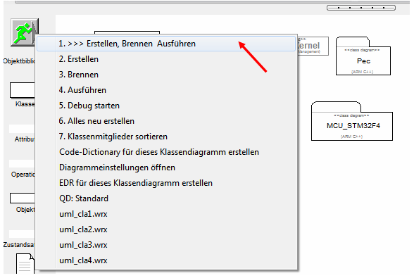
Compile the program. Correct typographical errors if necessary. Transfer the executable program to the program memory of the controller.
- Build (compile and link)
- upload
- the necessary elements …


Video summary
Learned and established work steps:
- Create and open class diagram
- Select and load diagram template for PEC application and insert driver package for STM32F0
- Look for PEC blocks from the library in Explorer
- Drag the desired library blocks and into the diagram
- Connect classes (aggregation, realization)
- Assemble components from system modules
- create the necessary source code in the operations
- Create and burn an STM32 application in the class diagram
And because it was so beautiful, here the whole thing again as a video.
Exercise
Expand the application by a second button with a UART terminal. Each time the button is pressed, a counter is to be counted up and sent to the SiSy control center at 19200 baud.