ESE Block 10 TIMER
Program your own timer. If you try to reduce the task of a microcontroller to the innermost being, to the core of the matter, you notice that in fact it is always about a certain behavior in a certain time. Called timing in technical slang. For embedded developers, timing and timers are inextricably linked. The number and possibilities of the timers of a microcontroller represent an essential performance feature. With the SysTick experiments and the generation of a PWM signal, we have actually already used timers. In this example we want to use a timer to generate our own timing via timer interrupt. The timer should trigger the counting up of an 8-bit counter and the sending of the counter to the SiSy-ControlCenter.
The task
 A microcontroller application is to be developed in which a timer acts as a trigger for a counter and the counter value is transferred to the PC.
The requirements for the solution are:
- The timer interrupt should be triggered every 50 milliseconds
- The counter should be an unsigned 8-bit number
- The data transmission should take place at 19200 baud
- The transferred values should be pure binary data
Preparation
Perform the following preparatory work:
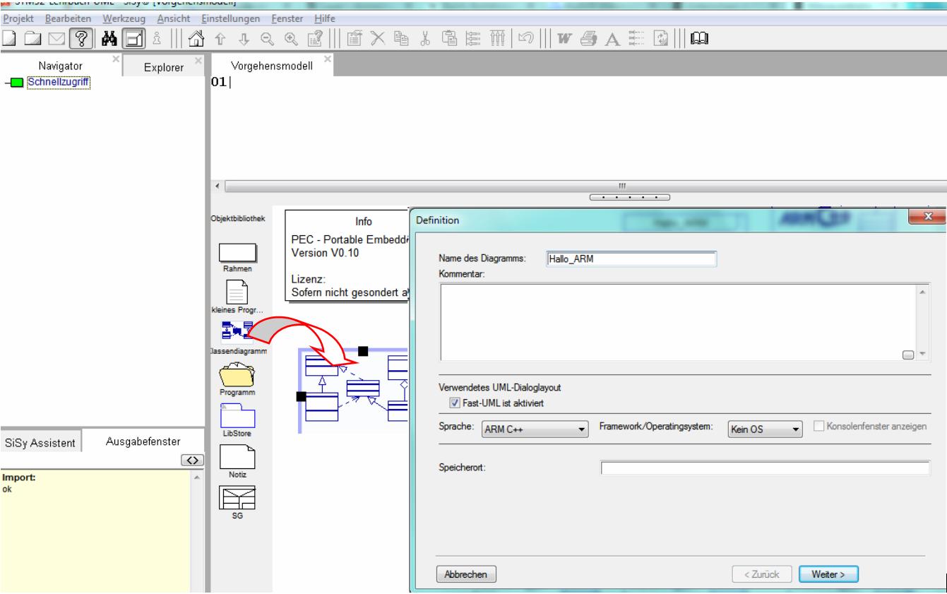
- create a new class diagram
- Target language ARM C ++
- Target platform STM32F042 mySTM32 Board light HAL
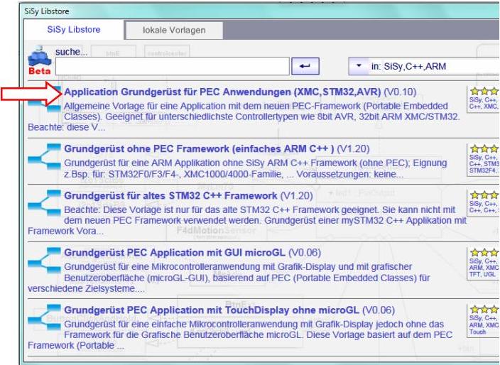
- Load diagram template application framework for PEC applications (XMC, STM32, AVR)
- Assign driver package for STM32F0
- optional template stm32F042_48Mhz assign

Solution idea
 The task is to build your own timer for triggering an action of the controller. The action to be triggered is represented by counting up a value and sending the value to the PC via UART. This action should be triggered regularly every 50 milliseconds. This time we have the special feature that a system component is not present as a visible element on the system board but is an internal component of the controller. This results in the following system components for our system:


In the PEC library we find the basic module PecTimer . In addition to a virtual onTimer() operation for handling the timer interrupt (event handler), it also offers various alternatives for initializing the timer configHz(), configMs(), configUs() . This pretty much relieves the developer of the usual timer calculation with prescaler, counter values, etc.

The following rough draft of the application solution results from what has been set out so far.

This rough draft can be read as follows:
The Controller class has a trigger and a terminal. The trigger is a PecTimer. The terminal is a PecUart with baudrate19200.
REMEMBER: internal system unit = is also an system block
Realization
The implementation should contain the elements described in the above draft. In addition, the following model elements must be added:
- the concrete timer for example Timer2
- the used UART 1 at port A9
- an 8-bit counter as an attribute of the trigger class
- Overwriting the onTimer() operation of the Trigger class
Use the following class diagram as a guide for these steps.


The timer is initialized to the required 50 milliseconds in the controller's start sequence. Note the following code in the onStart() operation of the Controller class.

Controller::onStart():void// boot sequence after start SysTick trigger.configMs(50);
We note the action to be triggered, increment the value and send it to the PC terminal in the operation onTimer () of the Trigger class as follows:

Trigger::onTimer():voidcounter++; app.terminal.writeByte(counter);
This application solution can now be tested. Vary the initialization of the timer, for example, to 5 milliseconds and check the result in the SiSy control center.
Test
Compile the program. Correct typographical errors if necessary. Transfer the executable program to the program memory of the controller.
- Connect the system board to the PC
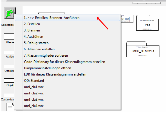
- Create application solution (compile and link)
- Transfer application solution (burn)
- Open and configure SiSy Control Center (COMx, 19200 baud)
- Connect and switch to Oszi view


Video summary
Learned and established work steps:
- Create and open class diagram
- Select and load diagram template for PEC application and insert driver package for STM32F0
- Look for PEC blocks from the library in Explorer
- Drag the desired library blocks and into the diagram
- Connect classes (aggregation, realization)
- create the necessary source code in the operations
- Create and burn an STM32 application in the class diagram
And because it was so beautiful, here the whole thing again as a video.
Exercise
To practice, expand the application by an LED that switches (toggle) with each trigger event.